Build & Configure
Hardware safety
Always disconnect the battery before touching any wiring. First builds rarely work on the first try — that is normal. Take it step by step and power off between changes.
A differential-drive robot controlled by an ESP32 over WiFi. The ESP32 receives /cmd_vel from iROSLink via Zenoh and drives two motors through an H-bridge. The phone mounts on top and handles all sensing and navigation.
Recommended order
Flash the firmware and verify the phone ↔ ESP32 connection before wiring any motors. The Serial Monitor shows every received /cmd_vel — you can confirm the full communication chain is working with just a USB cable.
Parts
| Component | Function | Approx. cost (USD) |
|---|---|---|
| Differential-drive chassis | Frame, motors, wheels, caster | $10–25 |
| ESP32 development board | Motor control over WiFi (e.g., ESP32 DevKitC) | $4–8 |
| L298N dual H-bridge driver | Drives two DC motors | $3–6 |
| 2S/3S LiPo battery (~11.1V) | Power | $10–20 |
| LiPo charger | — | $10–15 |
| iPhone mount | Holds phone landscape on chassis | $2–10 or 3D print yourself |
| Jumper wires, connectors | — | $2–5 |
Total estimate: $30–70 USD. Prices vary by region — AliExpress is cheapest, Amazon ships faster.
LiPo safety
LiPo batteries can catch fire if overcharged, short-circuited, or physically damaged. Use a proper LiPo charger and follow standard LiPo safety practices.
Safer alternative: USB-C PD power bank
If you want to skip LiPo handling entirely, use a USB-C PD Trigger Module (set to 12V output) connected to a PD-capable power bank. Most DC motors and the L298N run fine at 12V from PD.
What you need:
- USB-C PD trigger module set to 12V (search "PD trigger module 12V" — ~$2–4)
- PD power bank that supports 12V output (check spec — many 20,000 mAh banks do)
Benefits over LiPo: lower fire risk, no special charger, easy to recharge, travel-safe.
Trade-off: lower peak current than a direct LiPo — adequate for small chassis motors, may struggle with high-torque or large motors.
BOM coming soon
Specific chassis models, L298N vs alternatives, and tested configurations will be added in a future release. If you have a working setup, feel free to open an issue or PR.
Want to add a vacuum?
→ Vacuum Robot — fan ESC wiring, Explore and Clean modes
Step 1 — Flash the firmware
The firmware subscribes to /cmd_vel over Zenoh and drives the motors.
| ROS2 topic | Direction | Description |
|---|---|---|
/cmd_vel |
subscribe | Drive commands (geometry_msgs/Twist) |
/battery/voltage |
publish | Battery voltage every 10 s |
Install PlatformIO
Clone the iroslink-esp32 repo, install the PlatformIO IDE extension from the VSCode marketplace, then open the repo folder in VSCode. PlatformIO installs all dependencies including zenoh-pico automatically.
Add WiFi credentials
Edit include/secret.h:
#define WIFI_NETWORKS \
    { "home-network",   "home-password"   }, \
    { "office-network", "office-password" }   // add as many as needed

#define ROUTER_MDNS_HOST "iphone"   // e.g. "iphone" → connects to iphone.local:7447
The firmware tries each WIFI_NETWORKS entry in order (8 s timeout per network, loops until one connects). The Zenoh router is discovered via mDNS first, then falls back to the WiFi gateway, then 192.168.2.1.
Flash
- Plug the ESP32 in via USB-C (newer boards) or micro-USB (older boards) — no motor wiring needed yet.
- In VSCode: PlatformIO sidebar →
esp32dev→ Upload. - Open Serial Monitor after flashing (baud rate set automatically).
LED status (GPIO 2 onboard LED):
| Pattern | Meaning |
|---|---|
| Fast blink — 100 ms on / 100 ms off | Connecting to WiFi |
| Slow blink — 100 ms on / 2 s off | Connecting to Zenoh router |
| Single flash on each message | cmd_vel received and applied |
| Slow blink — 1 s on / 1 s off | No cmd_vel for >500 ms — motors stopped, waiting |
Expected output once connected to WiFi:
Connecting to WiFi... OK — IP: 192.168.x.x
mDNS: mypc.local → tcp/192.168.x.x:7447
Opening Zenoh Session... OK
>> cmd_vel  lin.x=0.500  ang.z=0.000  lag=3ms  10.0Hz
bat=11.82V
Step 2 — Configure the app & verify over UART (no wiring needed)
Configure iROSLink first, then confirm the full communication chain works — all with just the USB-connected ESP32 and your phone on the same WiFi network.
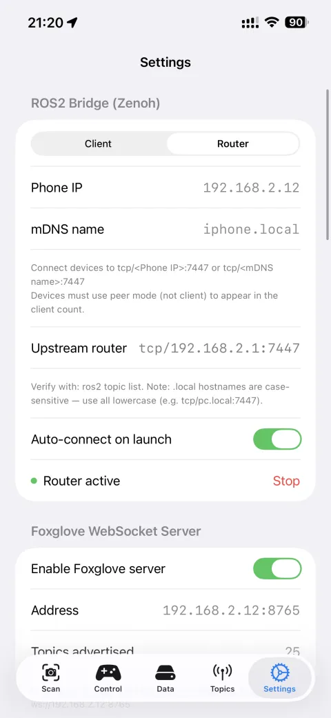
Configure Zenoh
Open iROSLink → Settings → ROS2 Bridge (Zenoh).
Router mode (recommended for most setups): the phone acts as the Zenoh hub; ESP32 and any desktop nodes connect to it.
- Select Router.
- Note the IP and mDNS hostname shown — e.g.
192.168.1.42/iphone.local. - In
secret.h, setROUTER_MDNS_HOSTto the phone's mDNS name (e.g.iphone), then re-flash.
Enable Auto-connect on launch once everything is working.
Client mode
If your desktop already runs a Zenoh router (rmw_zenohd), you can switch the phone to Client mode and point it at the desktop instead. This lets the desktop be the network hub and reduces phone radio load — useful for extended sessions. See → Zenoh Networking for setup details.
Verify
- Watch the Serial Monitor — you should see
Opening Zenoh Session... OK. - In iROSLink → Settings tab — the robot connection indicator should show connected (visible in Autonomous IDD mode only).
- In iROSLink → Scan tab — a robot connection badge also appears here in Autonomous IDD mode.
- In iROSLink → Control tab → move the joystick.
The Serial Monitor should print:
If you see those lines, the phone is reaching the ESP32 over WiFi. Motor wiring can now proceed with confidence.
Known limitation — disconnect not detectable mid-session
If the Zenoh router (phone) goes offline after the ESP32 session is established, the ESP32 cannot detect this immediately. The ESP32 will auto-reconnect within ≤30 s via lease expiry. During this window the LED may not show a "reconnecting" pattern. A 5-minute silence watchdog restarts the ESP32 as last resort if cmd_vel never returns.
Tip
Try the joystick at full range — watch that lin.x and ang.z values respond correctly. No risk to hardware since nothing is wired yet.
Step 3 — Wire the motors
Only proceed once Step 2 passes.
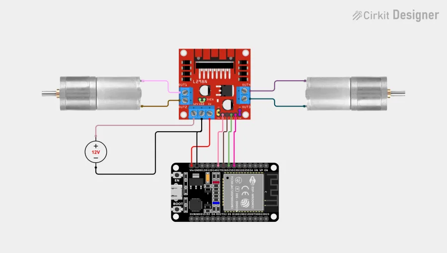
ESP32 pin assignments
| Signal | ESP32 GPIO |
|---|---|
| Left motor IN1 | 25 |
| Left motor IN2 | 33 |
| Right motor IN1 | 26 |
| Right motor IN2 | 27 |
| Battery ADC | 34 |
| Boot button (onboard) | 0 |
Circuit diagram
Wiring notes
- GPIO 0 is the onboard BOOT button — no external wiring needed.
- GPIO 34 is ADC-only (input, no pull-up) — battery voltage divider connects here.
- The L298N 5V pin can power the ESP32 via its onboard 5V regulator.
Warning
Double-check motor polarity before powering on. Reversed motor wires cause the robot to spin in place instead of driving straight, and in some H-bridge configurations can draw excess current.
Running with ROS2 directly (Linux)
→ ROS2 Teleoperation (Linux) — Zenoh router setup, keyboard and gamepad teleoperation, verify commands reach the robot
Step 4 — Mount the phone
How you mount the phone affects odometry, SLAM, and depth sensing quality.
- Mount landscape (horizontal). Vertical orientation causes odometry errors.
- Camera and LiDAR face forward — toward the direction the robot drives.
- Keep LiDAR's forward view clear. Do not block it with wiring or cables.
- Mount flat and level. Tilt introduces a constant bias in depth-to-floor measurement.
- Mount rigidly. Use a firm mount with grip material (silicone, rubber) — flex or vibration adds noise to IMU and odometry.
Note
SLAM is compute-intensive. The phone may get warm during extended sessions — this is normal.
Camera height
The LiDAR uses the phone's height above the floor to separate ground points from obstacles.
- Control tab → Occupancy Grid → Auto-detect camera height is on by default.
- If auto-detect is unreliable (thin carpet, textured floor), disable it and set
gridCameraHeightmanually. Measure from the floor to the LiDAR lens.
Step 5 — Final app settings
Zenoh was already configured in Step 2. This step covers topics and robot dimensions.
→ Tuning topic rates and image quality — adjust rates or disable topics for slow WiFi or sensors-only setups.
Robot dimensions (Autonomous IDD only)
Control → Configuration → Robot Body
Used for collision checking. Inaccurate values cause the robot to clip obstacles.
| Setting | What to measure | Typical range |
|---|---|---|
| Robot length | Front-to-back | 0.15 – 0.60 m |
| Robot width | Side-to-side | 0.15 – 0.60 m |
| Camera from left | Distance from left face to camera | 0 – robot width |
Also set Occupancy Grid → Camera Height: - Enable Auto-detect to let LiDAR measure it from the floor. - Or enter manually in centimetres.
Connect and verify
- Tap Connect in the Settings tab.
- Status:
Disconnected → Connecting… → Connected (N peers). - If stuck at
Connecting…after 10 s → Troubleshooting.
Once connected, open Scan tab → tap Start SLAM. You should see:
- Point cloud building as you move the phone
- Tracking state: Normal (yellow/orange = degraded, red = lost)
- Odometry publishing (check Topics tab for live Hz)